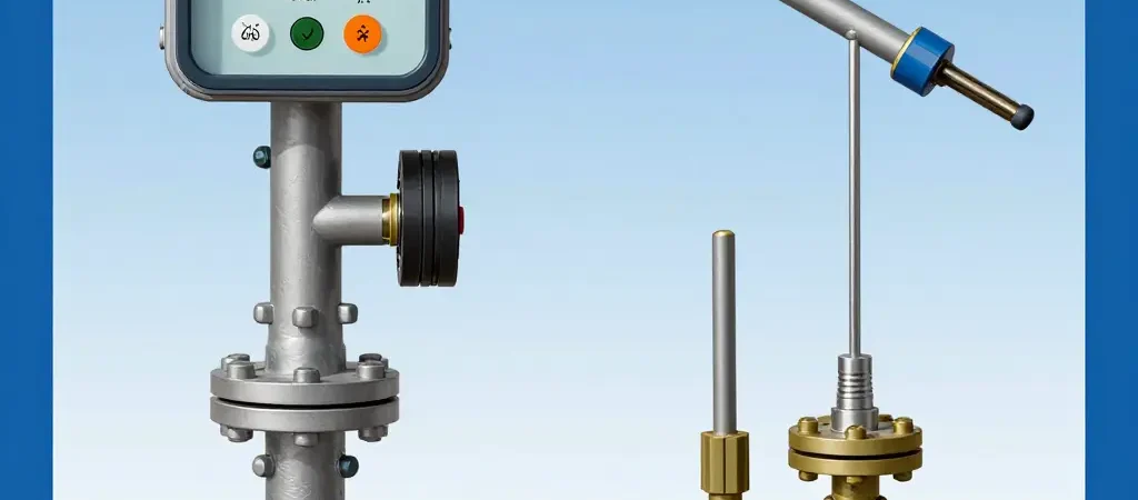
Pressure Transmitter Selection on High-Vibration Lines: Diaphragm Seal or Direct Mount
On a vibrating line, pressure transmitter selection reduces to one choice: isolate the instrument behind a diaphragm seal, or bolt it straight onto the process connection. Either arrangement reads pressure accurately while the line is quiet. They diverge once a pump, compressor, or pipe is pushing continuous oscillation into the tap. That choice sets how long the transmitter lasts and how much you can trust its signal.
Cyclic stress from vibration fatigues threaded joints, backs off fittings, and grows cracks in thin sensor housings and welded diaphragms. A transmitter rarely fades out gracefully; the signal goes bad, and the first person to notice is often the one cleaning up after a process upset.
The two options also fix different things. Direct mounting keeps response fast and the installation simple. A diaphragm seal puts a fluid-filled barrier between process and sensor; depending on how you specify it, that barrier either protects the sensor or becomes a new set of failure points. Specify it wrong and you buy the instrument twice – once at purchase, again at each unplanned shutdown.
What follows covers how vibration damages pressure measurement, how each mounting approach behaves, the criteria worth weighing, installation practice, and a decision path for matching a mount to a specific line.
Transmitters on vibrating lines fail in ways that static-service instruments never see. Service life shortens, calibration drifts, and readings wander for reasons that are hard to trace back to vibration, because the damage builds up over months instead of announcing itself in one event. Each failure path needs its own countermeasure, from a stiffer mount to better loop shielding.
Fatigue, Loosening, and Sensor Degradation
Welds and process connections take the worst of it. Every vibration cycle strains the diaphragm-to-body weld and the threaded or flanged joint a little; after millions of cycles, microcracks start at stress concentrators such as weld toes and thread roots and grow until the wall leaks or the joint breaks. Threaded joints fail a different way: micro-slip between mating threads bleeds off preload until the joint backs off and the seal is lost. Both modes get worse when a direct mount clamps the transmitter to an excited pipe and feeds piping energy straight into the instrument.
Resonance can look like an electrical fault while actually being mechanical. A transmitter’s natural frequencies depend on its mass, its mounting, and the stiffness of the connection. When piping excitation lands near one of them, diaphragm motion is amplified and the output picks up error and broadband noise that field calibration cannot remove. Mechanical strain also accumulates in the diaphragm and in the strain-gauge bond, changing the element’s properties so the zero and span creep even while the electronics keep working.
Vibration also loosens cable glands and connectors, and the resulting intermittent contact turns into microphonic spikes on a 4-20 mA signal. The control system sees corrupted data while the sensing element is still fine. Because these mechanisms compound, selection for vibrating service comes down to trading mounting isolation against response time and cost.
Vibration Sources and Resulting Failure Modes
Vibration seldom kills a transmitter outright. It wears the instrument down through fatigue, loosening, and unstable signals. Knowing which sources cause the damage helps decide whether a seal or a direct mount protects better.
- Reciprocating pumps – Pulsating pressure waves at the plunger or piston frequency stress the sensor diaphragm and fatigue-crack the weld or process connection.
- Centrifugal compressors – High-frequency rotor vibration loosens threaded fittings and can shear the mounting bracket of a directly mounted transmitter.
- Turbulent, high-velocity flow – Broadband random excitation speeds up diaphragm metal fatigue and erodes the isolating diaphragm surface.
- Piping resonance – Amplified machine vibration becomes large-amplitude oscillation that snaps capillary tubing and produces noisy or erratic output.
- Cavitation and flashing – Intense localized pressure spikes (micro-jets) pit the diaphragm surface, causing drift and eventual perforation.
- Slug or two-phase flow – Sharp, repetitive impact loads strike the diaphragm seal, cracking the isolating element and disrupting the process seal.
- Water hammer and surge events – Sudden high-energy pressure transients deform the diaphragm and permanently shift the transmitter’s calibration.
- Sustained mechanical loosening – Long-term shaking relaxes bolt preload until the transmitter rotates or vibrates freely and the electrical connections and seals fail.
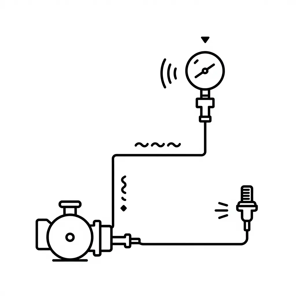
How Vibration Reaches a Transmitter: A Simple Two-Path Schematic
The schematic below reduces the problem to its essentials. A rotating source – pump, compressor, or mixer – pushes mechanical energy into the process piping, and that energy travels as a vibration wave. Where the wave ends up decides everything.
Reading the Two Paths
- Direct mount (top path): The transmitter bolts directly to the pipe with nothing in between. The wave runs from the pipe wall into the housing, so sensor, electronics, and process connection all absorb it. That is the shortest, stiffest coupling – and the hardest on the instrument.
- Diaphragm seal with capillary (bottom path): The pipe feeds a diaphragm seal, which connects to the transmitter through a thin, flexible capillary tube. The capillary decouples the two mechanically, so far less vibration energy reaches the instrument. The faint arrows at the far right show that attenuation.
Why the Geometry Matters
How much vibration reaches the transmitter depends on the stiffness and mass of the connection between pipe and instrument. A short, rigid connection passes nearly all of it through. A longer, flexible, heavier-coupled one sheds a real share of the energy before it arrives. Most rules of thumb for high-vibration installations trace back to that one fact.
The rest of the article turns that principle into selection criteria: piezoresistive, capacitive, and strain-gauge sensor technologies, fill fluids, mounting brackets, and the trade-offs that come with choosing isolation over simplicity.
Direct Mount Fundamentals: Mechanical Coupling and Vibration Exposure
A direct mount pressure transmitter connects straight to the piping through a threaded fitting (NPT, BSPP) or a flange (ANSI, DIN), with the sensing element mechanically coupled to the pipe wall. There is no impulse line, no capillary tubing, and no fill fluid between process and diaphragm. Process pressure pushes on the isolating diaphragm, which passes the force straight to the sensor inside the transmitter housing.
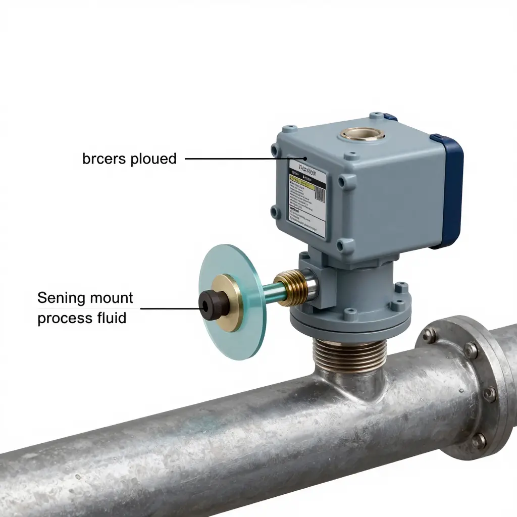
The rigid coupling has real benefits. Without a fluid column to lag the signal, response is fast; without fill fluid, there is no thermal error from it; without a capillary, there is nothing to clog, freeze, or leak. The installation is compact and inexpensive, which is why direct mount is common on water, air, hydraulic, and clean-fluid service. The trade-off is that the same rigidity that buys the fast response also removes any isolation between line and instrument.
Cantilevered off the pipe, the transmitter passes every vibration mode of the line straight into the housing, its mounting threads, and the sensor assembly. On pump discharge headers, compressor suction, and reciprocating-equipment skids, its mass acts as a mechanical amplifier. Sustained oscillation can loosen threaded joints, fatigue the process connection, and inject noise into the signal when the vibration frequency approaches the sensor’s natural frequency.
Direct mount is still the right, inexpensive choice where the process is clean and non-clogging, the temperature stays within the transmitter rating, and line vibration is low to moderate; there it usually costs less and installs faster than a remotely sealed arrangement. On vibrating service, assess vibration severity, fluid characteristics, temperature, and serviceability before defaulting to a diaphragm seal – direct mount is often sufficient once the environment has actually been measured.
Diaphragm Seal Mounting Fundamentals
A diaphragm seal keeps the transmitter away from a process that its sensing element cannot directly tolerate. A thin, flexible separating diaphragm sits at the process connection; behind it, fill fluid carries pressure hydraulically to the transmitter body through a capillary or a short direct-mount nipple. The transmitter touches only fill fluid, and the process touches only the seal diaphragm and its wetted surfaces. That arrangement dictates how and where the transmitter can be mounted on a given line.
The seal buys two things: isolation and damping. The separating diaphragm and the contained fill fluid column form a compliant, viscous layer that absorbs high-frequency pressure pulsations before they reach the sensing element. On lines driven by reciprocating compressors, pumps, or fast-acting valves, that damping keeps noise from swamping the measured signal and reduces fatigue loading on the sensor. Fill fluid also slows heat transfer, so a hot or cold process does not immediately shock the transmitter body, protecting both the sensor and its electronics from abrupt temperature swings.
Those advantages carry measurable trade-offs that have to be quantified during selection. Diaphragm stiffness, temperature-driven fill-fluid expansion, and capillary orientation all add uncertainty, so total accuracy is usually worse than a direct-mounted gauge. As the fill fluid changes density with temperature, zero and span shift; a long capillary adds response lag because the fluid has to move before pressure equalizes. A height difference between seal and transmitter also adds a head-pressure offset.
| Mounting factor | Direct mount | Diaphragm seal with capillary |
|---|---|---|
| Vibration damping | Minimal | High |
| Thermal isolation | Low | High |
| Response time | Fast | Slower |
| Added error sources | Few | Several |
A diaphragm seal is a thermal and mechanical buffer, not a universal upgrade, and its costs scale with capillary length, fill-fluid choice, and the temperature differential across the installation.
Choosing the right interface on a vibrating line means weighing how each approach handles mechanical stress against its effect on accuracy and upkeep, as the table below summarizes.
| Comparison Criteria | Direct Mount | Diaphragm Seal |
|---|---|---|
| Vibration tolerance | Low; transmitter body absorbs line vibration directly | High; flexible capillary and fill fluid decouple the sensor from vibration |
| Measurement accuracy | High; no fill-fluid or capillary error sources | Slightly reduced; fill-fluid temperature effects introduce minor offset |
| Response time | Fast; pressure acts directly on the sensor diaphragm | Slower; fill fluid and capillary length add measurable lag |
| Temperature exposure of the sensing element | High; sensor sees full process temperature at the tapping point | Lower when remote-mounted; capillary isolates the sensor from process heat |
| Installation complexity | Simple; screws straight into the process connection | Complex; requires seal, capillary routing, and careful mounting |
| Maintenance effort | Minimal hardware, but frequent recalibration on harsh lines | Higher setup complexity, but less sensor drift and fewer recalibrations |
| Initial cost | Lower; fewer components and fittings | Higher; seal, capillary, and fill fluid raise unit cost |
| Typical service life under vibration | Shortened; continuous vibration accelerates sensor and electronics fatigue | Extended; mechanical isolation protects the sensing element over time |
On high-vibration service, the seal’s mechanical isolation usually outweighs its higher cost and slower response, and it lasts longer when sensor reliability is the priority.
A Step-by-Step Decision Framework for Mounting Selection
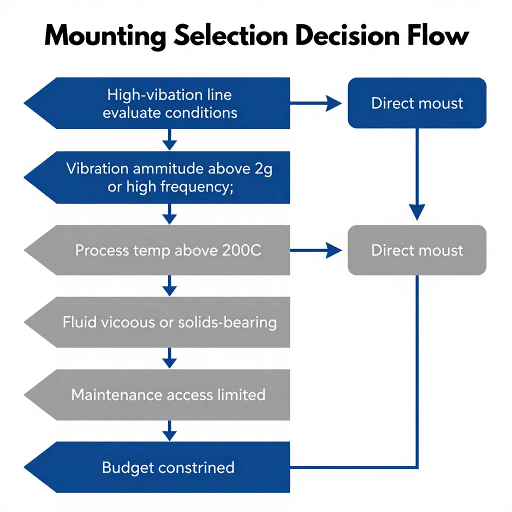
The choice between direct mount and a diaphragm seal is rarely about preference. It is about which process variable will break the installation first. To keep the decision repeatable, work through six variables in order: vibration amplitude and frequency, process temperature, fluid viscosity and solids content, required measurement accuracy, maintenance access, and budget. Start from direct mount – simpler, cheaper, no capillary lag – and escalate to a diaphragm seal or remote mount only when one variable fails its check.
Begin with vibration. Measure or estimate amplitude (in g or mils) and the dominant frequency. Strong periodic excitation from a pump, compressor, or nearby piping can fatigue a directly threaded transmitter at the process connection, loosen fittings, and shift its calibration. Direct mount is acceptable at low amplitude and low frequency, but once the line exceeds roughly 2 g or carries sustained high-frequency excitation, a diaphragm seal with a remote capillary isolates the sensor from that mechanical load. Temperature follows the same logic: above about 200 C, or beyond the sensor’s rated limit, a seal with a capillary or extended diaphragm keeps the electronics within their operating range.
Screen fluid and accuracy together. Viscous streams, slurries, or fluids carrying solids will clog a direct-mounted port and force frequent cleaning, so a diaphragm seal with a flush or extended diaphragm is the practical answer. But a remote seal also adds temperature error and capillary lag; if the application demands tight measurement accuracy, keep the capillary short, apply compensation, or stay with direct mount on a clean, low-vibration line. Fluid behavior and accuracy often pull in opposite directions, which is why they are evaluated as a pair rather than in isolation.
Finally, weigh maintenance access and budget. On a hot, crowded, or hard-to-reach header, a remote-mounted seal lets technicians service the electronics without breaking into the process, cutting downtime even though the hardware costs more. Budget then decides among the surviving options: direct mount costs the least, a cored seal is mid-range, and a fully remote capillary system is the premium choice. Let the most limiting variable set the mounting class, then use cost to choose within it. Put the six checks on a one-page worksheet so any engineer can reproduce the same decision for the next line.
Decision Framework: Choosing Between Direct Mount and Diaphragm Seal
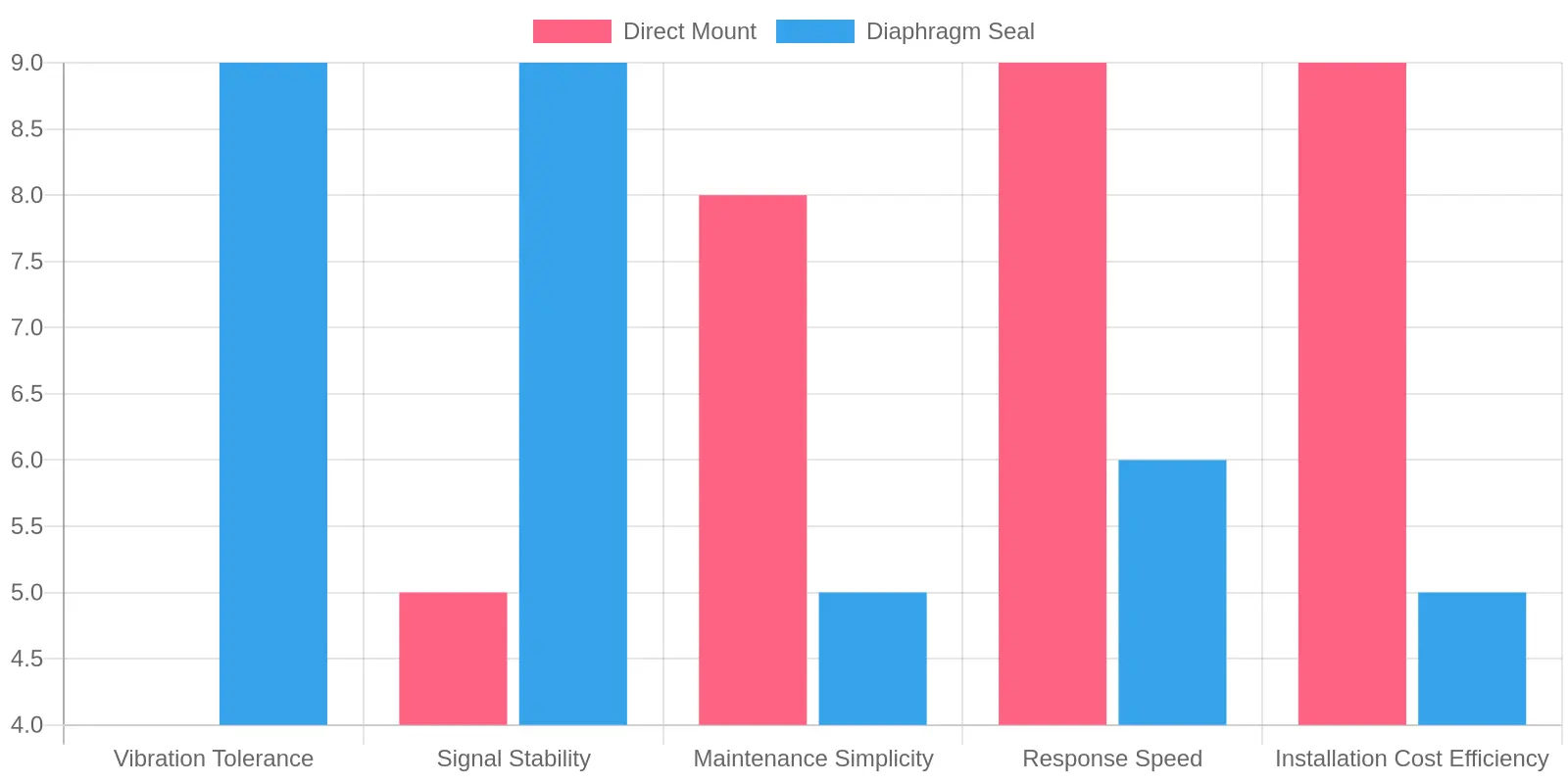
Faced with a vibrating process line, most people reach for the cheapest, simplest mount. That instinct is often right – but only when the application cooperates. Scoring both approaches on the dimensions that actually matter in high-vibration service makes the call objective: vibration tolerance, signal stability, maintenance simplicity, response speed, and installation cost efficiency.
The grouped bar chart below scores both approaches on a 0-to-10 scale, where 10 represents best-in-class performance. A higher bar is not automatically “better” for your process – it simply shows where each design shines and where it gives ground.
Reading the Chart
The pattern is clear at a glance. Direct Mount wins on the three dimensions tied to simplicity and speed – maintenance simplicity (8 vs. 5), response speed (9 vs. 6), and installation cost efficiency (9 vs. 5). There is no extra hardware, no fill fluid, and no capillary to route or lag, so the transmitter responds almost instantly to pressure changes and costs less to install.
Diaphragm Seal wins where surviving vibration matters. It scores 9 versus 4 for vibration tolerance and 9 versus 5 for signal stability. The isolating diaphragm and fill fluid mechanically decouple the sensor element from the pipe, soaking up high-frequency energy that would otherwise fatigue the process connection and corrupt the measurement.
The Scores at a Glance
| Performance Dimension | Direct Mount | Diaphragm Seal |
|---|---|---|
| Vibration Tolerance | 4 | 9 |
| Signal Stability | 5 | 9 |
| Maintenance Simplicity | 8 | 5 |
| Response Speed | 9 | 6 |
| Installation Cost Efficiency | 9 | 5 |
Turning the Ratings Into a Decision
Treat these scores as a weighted checklist rather than a raw popularity contest. The logic breaks down cleanly:
- Choose Direct Mount when vibration is mild to moderate, the process fluid is clean and non-clogging, and you value fast response and low installed cost. The high marks for response speed and cost efficiency translate directly into lower capital spend and quicker loop tuning.
- Choose a Diaphragm Seal when vibration is severe or continuous, or when the fluid is viscous, corrosive, or prone to solidifying. The isolation the seal provides pays for itself by protecting the measurement and extending transmitter life, even though you sacrifice some response speed and take on extra maintenance overhead.
- Consider a hybrid approach – a remote-mounted diaphragm seal with a short capillary – when you need both vibration isolation and a serviceable transmitter position. It captures much of the seal’s stability while clawing back some maintenance simplicity.
There is no universal winner on this chart. The right mounting approach is whichever one matches the dominant physical threat on your line – vibration or complexity. Score your own process against these five dimensions, and the decision usually makes itself.
Installation and Mounting Best Practices for High-Vibration Lines
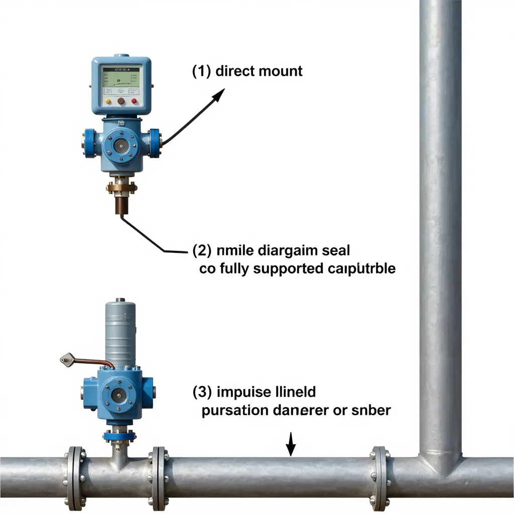
Mounting Measures That Extend Transmitter Service Life
On high-vibration lines, how the instrument is mounted matters as much as which instrument you chose. Even a correctly specified sensor can fail early if its mounting hardware amplifies vibration rather than resisting it. Work through the following measures in order, starting at the mechanical interface and moving out to the process connections and any secondary sensing components.
Rigid mounting brackets are the foundation. A transmitter body that is allowed to flex will accumulate fatigue at internal welds, diaphragm assemblies, and electrical terminations. Use heavy-gauge, factory-approved brackets, and anchor the transmitter to a structural member instead of the vibrating pipe wherever practical. In a direct mount configuration, the bracket must transfer dynamic loads into stiff structure while keeping the process connection free of bending stress.
Impulse line routing and damping deserve equal attention. Run impulse lines with adequate slope and support them independently so that pipe motion is not transmitted into the instrument. Where vibration cannot be eliminated at the source, install damping or isolation devices – such as snubbers, pulsation dampeners, or flexible isolation elements – as close to the transmitter as possible.
Correct torque on process connections matters too. Under-torquing invites leaks and gradual loosening under cycling loads; over-torquing can crack fittings and pre-load the sensing element, shifting its zero point. Follow the manufacturer’s torque specification and use a calibrated wrench rather than estimating by feel.
When a diaphragm seal is used, support the capillary tubing along its full run with clamps that prevent whipping and resonance, and avoid tight bends that concentrate stress. Orient the seal so the diaphragm face is self-draining and shielded from direct impact or turbulent flow. Applied together, these measures reduce the mechanical stress that vibration imposes on the complete measurement assembly and extend the intervals between calibration and repair.
Mounting Selection Decision Framework
Before you commit to a hardware configuration, walk the vibration question in sequence: measure the line, check amplitude against nozzle limits, verify temperature and process compatibility, then branch. The flowchart below captures that logic in a single visual pass, moving from the starting evaluation node through the decision diamonds and resolving into the final fork between a direct mount and a diaphragm seal. Because it is deliberately label-free, it works as a quick logic map you can annotate with your own site-specific thresholds.

Read it left to right: follow the arrows, answer each diamond against your measured data, and the terminal rectangle tells you which installation family the application calls for. If you keep looping back to the start, that is your signal to escalate toward the more protective sealing option.
A Repeatable Step-by-Step Selection Sequence for High-Vibration Lines
When a pressure tap sits on a pump discharge, compressor skid, or reciprocating machine, the wrong mounting choice fails long before the sensor electronics wear out. The sequence below gives engineers and maintenance teams a consistent, repeatable method for every vibrating line in the plant, from the first measurement to the final post-installation check.
- Measure or estimate the line vibration at the proposed tap location using an accelerometer or triaxial vibration meter, capturing both peak amplitude and dominant frequency.
- Convert those readings into acceleration (g) or velocity (in/s) values and compare them directly against the transmitter manufacturer’s published vibration rating.
- Record the process temperature, pressure range, fluid chemistry, and ambient conditions at the tap so the sensor body, wetted parts, and seals are correctly matched to the service.
- Decide whether a direct-mount transmitter can survive the measured vibration or whether a remote diaphragm seal with a capillary is required to isolate the sensor.
- Choose the sensor technology (piezoresistive, capacitive, or strain-gauge) that best tolerates the vibration frequency while still meeting the required accuracy class.
- Specify the mechanical mounting and orientation, including brackets, impulse line routing, and any isolation that keeps the diaphragm face free from resonance.
- Add damping and signal filtering (electronic damping, snubbers, or averaging) so vibration-induced noise does not corrupt the 4-20 mA output.
- Install the assembly using the correct torque and support hardware, then torque-check fittings to prevent loosening under continuous cycling.
- Verify performance after installation by re-measuring local vibration and confirming the transmitter output is stable, then log a baseline reading for future trending.
Following this order keeps the decision objective rather than reactive, and it ties directly into the decision framework so that diaphragm-seal versus direct-mount choices are justified by data instead of habit.
How the Mounting Decision Plays Out Across Industries
Which mount wins depends on mechanical stress and fluid behavior together, not on preference. In oil and gas, upstream and midstream lines routinely combine high-frequency pump and compressor vibration with fluids that carry sand, hydrogen sulfide, or wax. A diaphragm seal is generally favored here because it isolates the sensing element from both the abrasive medium and the vibratory energy transmitted through rigid process connections, extending service life and reducing drift. Downstream, on clean, dry gas lines where vibration is moderate and the fluid is benign, a direct mount remains economical and responsive enough to justify its simpler installation and lower maintenance.
Chemical processing exposes instrumentation to a different constraint: aggressive or polymerizing media that will attack wetted parts or clog a small impulse line. A diaphragm seal is the default choice regardless of vibration level, because corrosion resistance, temperature isolation, and a fill fluid tailored to the process outweigh the cost premium. Direct mount is reserved for compatible, low-viscosity streams on low-vibration skids, where the shorter impulse path improves response time and the reduced assembly complexity lowers installation cost.
Water treatment occupies the low-vibration end of the spectrum. Most municipal and industrial water and wastewater lines operate with predictable flow and modest pulsation, so selection typically tilts toward direct mount for its accuracy, fast response, and minimal maintenance. A diaphragm seal is introduced only where the medium is sludge-laden, chemically dosed, or prone to scaling, since the flush, obstruction-free diaphragm surface resists fouling that would otherwise blind an impulse line.
Power generation and food and beverage round out the range. In power plants, steam and condensate services combine thermal cycling with significant vibration, pushing engineers toward diaphragm seals with capillary or direct-mount configurations depending on accessibility. In food and beverage, the governing factor shifts again to hygiene: sanitary diaphragm seals with flush, crevice-free surfaces satisfy clean-in-place requirements, and vibration tolerance becomes a secondary benefit rather than the deciding factor. Across every sector, the recurring logic is consistent – high vibration or problematic fluid chemistry points to a diaphragm seal, while clean service and stable lines favor direct mount.
FAQ: Pressure Transmitter Selection on High-Vibration Lines
These are the questions engineers and maintenance teams raise most often when working through selection for high-vibration lines.
Is a diaphragm seal always required on high-vibration lines?
No, a diaphragm seal is not mandatory on every high-vibration line. It becomes necessary when vibration is severe enough to risk mechanical fatigue at the process connection, or when the process fluid is corrosive, viscous, or prone to clogging. On moderately vibrating lines carrying clean fluids, a rigidly supported direct mount can run reliably for years.
How much vibration can a direct mount tolerate?
Most direct-mounted transmitters tolerate continuous vibration up to roughly 2 g peak at frequencies below 60 Hz, provided the mounting bracket is rigid and the impulse line is short. Above that range, fatigue cracking at the thread or weld root becomes the leading failure mode. Always check the manufacturer’s rated vibration specification rather than relying on a general rule.
Does fill fluid affect accuracy?
Yes. The fill fluid is part of the measurement path, so its thermal expansion and viscosity introduce measurable error. Silicone oil stays stable across a broad temperature range, while high-temperature fluids reduce thermal drift at the cost of slower response. Match the fluid to process temperature, not just to pressure range.
Does capillary length matter?
Yes. Longer capillaries hold more fill volume, which amplifies temperature-induced zero shift and slows response time. Keep capillaries as short as practical, and route them away from hot surfaces, sharp bends, and vibration nodes. A well-placed short capillary often outperforms a long one on a vibrating line.
How do I evaluate an existing installation?
Log the actual vibration level with a portable accelerometer at the mounting point, then inspect brackets, fittings, and recent calibration records for cracks or zero drift. If measured vibration exceeds the transmitter’s rated limit, or if you keep repairing mechanical damage, upgrade to a diaphragm seal on a remote mount. Document the findings so the next maintenance review has a baseline.
Can I keep the transmitter body off the line without using a fill-fluid seal?
Yes. You can remote-mount the transmitter and connect it with a short impulse line or capillary to isolate the electronics from heat and vibration. This hybrid approach reduces vibration exposure while keeping maintenance access simple, but it still requires a clean, non-clogging process fluid.
Quick selection reference
| Continuous vibration (g peak) | Recommended mounting |
|---|---|
| Under 1 g | Direct mount with a rigid bracket |
| 1-2 g | Direct mount, short impulse line, periodic inspection |
| 2-5 g | Remote mount with a capillary |
| Over 5 g | Diaphragm seal on a remote mount |
Conclusion: Consolidating the Selection Guidance
A diaphragm seal or a direct mount is an engineering judgment, not a preference, and it turns on four measurable variables: measured vibration severity, process temperature, fluid properties, and required accuracy. Vibration severity, quantified as peak acceleration or velocity at the mounting point, determines whether the transmitter can tolerate direct mechanical coupling to the pipe. Process temperature establishes whether the instrument electronics and fill fluid must be thermally isolated from the process. Fluid properties, including viscosity, corrosiveness, and the tendency to solidify or crystallize, dictate the need for an isolating barrier. Required accuracy sets the allowable total error budget, which a mechanical seal and its fill fluid both influence.
The logic follows from those variables. Choose a diaphragm seal when vibration severity is high, process temperature exceeds the transmitter’s rated limits, the fluid is viscous, corrosive, or prone to clogging, or the application demands tight accuracy with minimal drift; it isolates the sensing element from mechanical and thermal stress while presenting a flush or extended barrier to the process. Choose a direct mount when vibration is low and well characterized, temperatures are moderate, the fluid is clean and non-corrosive, and cost and mechanical simplicity carry weight. In borderline cases, the measured data, not assumption, should break the tie.
Selecting the correct mounting approach protects two things at once: the integrity of the measurement and the service life of the equipment. A transmitter subjected to conditions beyond its design basis will drift, fail prematurely, or produce readings that no calibration can trust. Matching the mount to the application preserves accuracy over the instrument’s full service interval and prevents the unplanned downtime that follows a failed installation. Quantify the environment first, then let vibration severity, temperature, fluid behavior, and accuracy requirements determine the mount.