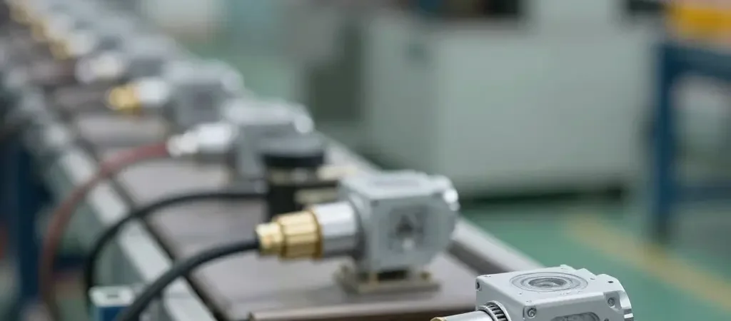
A pressure sensor drifts when its output slowly separates from the true pressure. On a production or workshop line, that quiet deviation usually traces back to two things technicians overlook: cable routing and grounding.
Drift is not a failure. A dead sensor stops working, sets a code, or drops to zero, and you know within minutes. Drift does none of that. It is a small offset that grows across shifts, temperature cycles, and thousands of operating hours, and because the signal stays plausible, it hides in plain sight.
On an assembly line or in an engine test cell, drifting readings show up as gradually biased fuel trims, brake or rail pressure checks that no longer repeat, and diagnostics that pass in the morning and fail by the afternoon. Technicians often reach for calibration, but recalibration treats the symptom. The offset comes back because nobody touched the physical cause.
Two physical causes deserve far more attention. The first is cable routing: signal cables that run beside motor drives, ignition coils, and VFD power feeds pick up induced noise that shifts the measured value. The second is grounding. Poor, floating, or shared ground references create potential differences the sensor reads as pressure, producing a steady bias that looks like a calibration problem.
Before replacing a sensor, inspect its wiring path and its ground reference. Most drift is found at the connector and the ground stud, not inside the sensor body.
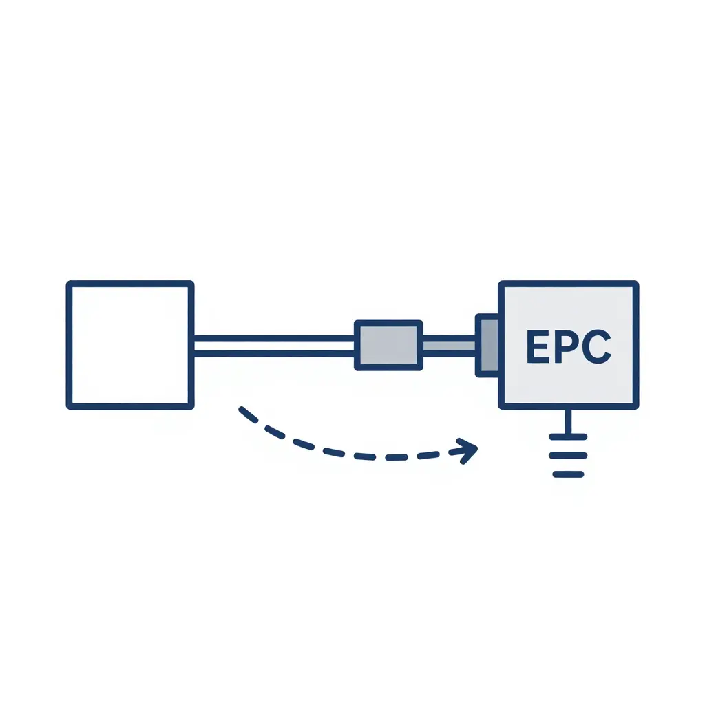
The schematic above traces the full path a pressure signal travels before it reaches a gauge or scan tool. The sensor element converts physical pressure into a small analog voltage; that voltage rides down the wiring harness, passes through one or more connectors, and arrives at the ECU/ADC input, where it is digitized against a ground reference point. The dashed loop arcing back along the harness marks where an electromagnetic interference source or a ground-loop potential adds voltage to the signal. When the ECU’s reference ground sits at a slightly different potential than the sensor’s ground, that difference does not vanish. It rides the harness and is summed straight into the reading, which is why a healthy sensor can still report phantom pressure drift and why chasing the component alone misses the fault in the routing and grounding.
Cable Routing: The Quiet Contributor to Drift
When a sensor logs a slow, load-dependent shift that recalibration will not erase, look at the harness before the sensor. How you route pressure sensor wiring relative to high-current conductors can inject errors that mimic drift almost perfectly.
High-current circuits – injectors, ignition coils, motors, and alternators – switch large currents quickly, building fast-changing magnetic and electric fields around their conductors. Route an analog signal cable parallel to one of these, and two coupling mechanisms act on it at once:
- Inductive coupling induces an electromotive force (EMF) along the signal loop wherever changing magnetic flux links the cable. The faster the current switches (di/dt), the larger the induced noise.
- Capacitive coupling injects displacement current through the parasitic capacitance between adjacent conductors, appearing as common-mode noise that rides on top of the true sensor voltage.
The result is a signal that wanders with engine or motor activity rather than pressure. Because the error starts as common-mode noise, a poorly grounded reference can convert it into a genuine differential shift.
Separation is the first countermeasure. Keep cable routing for sensitive signals well away from high-current runs, and where paths must cross, cross at 90 degrees to minimize loop area. Twisted-pair construction makes coupled noise common-mode so a differential input can reject it, while shielded cable with a single-ended shield ground blocks capacitive pickup.
Routing Best Practices
- Maximize separation distance from injector, ignition, motor, and alternator feeds.
- Cross high-current wiring at right angles – never run parallel.
- Twist signal pairs and terminate shields at one end only.
- Return sensor grounds to a clean, dedicated reference point.
Cable routing is part of signal design, not an afterthought. The drift you are chasing may already be sitting in the harness.
Cable Routing vs. Grounding: Symptom Comparison
The table below separates routing-induced noise from grounding-induced offset and loop errors, so you can tell them apart before swapping parts.
| Root Cause | Typical Drift Pattern | Diagnostic Indicator | Susceptible Conditions | Recommended Fix |
|---|---|---|---|---|
| Signal cable routed beside high-current wires (EMI/RFI pickup) | Fast, erratic jumps that spike with RPM or load | Reading settles when the cable is moved or shielded | Long parallel runs, unshielded wire, tight harness bundles | Separate signal and power paths; add shielding |
| Sensor leads run parallel to PWM or inverter cables (crosstalk) | High-frequency flutter synced to switching rate | Noise appears on a scope and clears after rerouting | PWM actuators, inverters, ABS pump circuits | Cross cables at 90 degrees; increase spacing; fit ferrite beads |
| Loose harness rubbing on a hot or moving part (intermittent contact) | Random dropouts tied to vibration or bumps | Wiggle test reproduces the fault on the scan tool | Engine mounts, suspension travel, sharp brackets | Reclip and anchor harness; replace chafed insulation |
| Sensor grounded at two separate chassis points (ground loop) | Slow, steady offset that wanders with temperature or load | Voltage measured between the two ground points | Multiple bonding points, corroded chassis joints | Single-point star ground; remove redundant grounds |
| Corroded or loose ground strap (high-resistance ground) | Gradual offset drift, worse when hot or wet | Ground-to-chassis resistance climbs above 0.1 ohm | Salt, moisture, aged or green-tinged wire | Clean, retorque, and add a star washer |
| Sensor shares a ground with a high-current load | Offset shifts the moment an accessory switches on | Reading changes with starter, fan, or light activation | Common ground bus, undersized wiring | Run a dedicated sensor ground return to the ECU |
Grounding: Offset Drift and Ground Loops
A pressure sensor never measures voltage in isolation; it measures voltage against a reference. When that reference moves, the reading moves with it. Poor grounding is one of the most misunderstood causes of pressure reading drift because the error usually looks like a clean, believable number rather than obvious noise.
Every transducer’s return current has to travel back to the controller through a conductor with finite resistance and inductance. That conductor is the sensor return path. On a 4-20 mA or 0-5 V channel, even small currents create voltage drops: V = I x R. A few milliamps through a shared ground lead with only 0.5 ohms of resistance develops millivolts of difference. The controller treats that shift as signal, so it appears as offset drift, not as a fault code.
A ground loop appears when two or more points connect to chassis or earth at slightly different potentials, driving circulating current and a ground potential difference between the sensor and the input. A common return shared by several sensors makes it worse: each sensor’s current modulates the same conductor, so one load changes another sensor’s reference.
Sound engineering principles:
- Tie all returns to a single-point star ground at one low-impedance node.
- Keep signal returns separate from power returns; never daisy-chain them.
- Minimize return-path resistance and keep loop current constant.
- Reference the ADC to the same node the sensor uses.
At 10 mV/psi sensitivity, a 5 mV ground shift is a 0.5 psi error – enough to fail a tolerance check and send technicians chasing the wrong part.
Field Checklist: Is It Cable Routing or Grounding?
Drifting pressure readings rarely come from a failed sensor alone, so work through these steps in order, moving from quick observation to full electrical isolation. Each step narrows the root cause until only one suspect remains.
-
Eyeball the harness first. Perform a full harness inspection: look for chafed insulation, pinched loom, corroded pins, and any sensor wiring routed beside ignition coils, injectors, or the alternator. It is fast, free, and it catches obvious problems.
-
Wiggle and flex the loom. With live data streaming, gently flex the harness by hand at connectors and bends. A reading that jumps means routing or a broken conductor, not a sensor fault.
-
Check routing proximity. Trace the pressure sensor cable and note how close it runs to high-current loads. Crosstalk only matters when wires share a path, so separation often removes the symptom instantly.
-
Measure ground potential difference. Back-probe the sensor ground and battery negative with the key on. Anything above roughly 50 mV reveals a ground potential difference feeding the signal.
-
Test the return path resistance. Ohm the sensor ground back to the PCM or chassis point. High resistance in the return path mimics drift because the reference floats with load current.
-
Scope the signal, loads off. Capture the pressure signal with every accessory off. A clean, steady trace here means the sensor and its wiring are likely healthy.
-
Scope the signal, loads on. Switch on fans, lights, and A/C, then repeat. New noise or drift confirms an induced or ground-shared error tied to routing.
-
Swap the sensor to isolate. Drop in a known-good unit. If the drift vanishes, the sensor failed; if it persists, wiring or grounding is still the root cause.
-
Re-route, then re-test. Finally, physically separate or shield the harness from noisy neighbors and re-measure. A clean reading proves routing; no change points firmly back to grounding. When diagnostic bills start rivaling the car’s value, sometimes replacing the vehicle is the smarter call.
Where Does Pressure Sensor Drift Actually Come From?
When a sensor reports a shifted or sluggish reading, the temptation is to blame the sensor itself. The breakdown below is our estimate of where drift actually comes from across the field failures we see, and it tells a different story:
| Root Cause | Share |
|---|---|
| Cable Routing / Induced Noise | 34% |
| Grounding / Ground Loop | 29% |
| Sensor Element Degradation | 18% |
| Connector Contamination | 12% |
| Supply Voltage Variation | 7% |
| Total | 100% |
Caption: Cable routing and grounding together account for just under two-thirds of drift complaints (34% + 29% = 63%). The sensor element itself is the culprit in fewer than one in five cases, so a harness and ground audit should come before the parts cannon – and before a shop decides a vehicle is more trouble than it is worth to sell for cash.
A Repeatable Diagnostic Workflow
Pressure sensor drift rarely announces its true cause, which is why seasoned technicians distrust a single suspect reading. A disciplined diagnostic workflow lets you separate cable routing from grounding in a predictable order.
Step 1 – Observe the drift. Record the sensor output cold, warm, and under load. Note whether the error appears instantly or builds slowly over time.
Step 2 – Isolate the harness environment. Reroute signal wires away from ignition coils, alternators, and high-current feeds. If noise isolation changes nothing, routing is likely innocent.
Step 3 – Test grounding integrity. Measure resistance from the sensor’s ground pin to battery negative. Anything above roughly 0.1 ohm, or a voltage drop that climbs with temperature, points firmly to grounding.
Step 4 – Confirm the fix. Re-run the same loads and conditions and compare against your original baseline log before declaring success.
Once you know their signatures, the two failure modes are easy to tell apart. Routing-driven noise is load-dependent and frequency-correlated: it tracks RPM, injector firing, or fan cycling. Grounding-driven offset is steady and position- or temperature-dependent: it shifts when the harness flexes or the bay warms up, yet stays flat when electrical load changes.
Documentation ties the method together. Photograph the as-found routing, log resistance and voltage-drop baselines, and record ambient and coolant temperatures. A written baseline makes results reproducible, so the next technician inherits hard data instead of starting from zero.
Change one variable at a time; otherwise you cannot tell which fix worked.
Cable Routing: Wrong Way vs. Right Way
On the left, the sensor cable hugs the high-current wiring, running parallel and bundled tight, so switching noise from the power conductors couples straight into the low-level sensor signal. On the right, the same cable is routed with clear physical separation and a shielding wrap. Same sensor, same load, two very different readings.
Frequently Asked Questions
How do I tell whether drift comes from cable routing or grounding?
Run the sensor with its harness routed exactly as installed, then compare readings against a bench test with short leads. If the reading drifts only in the vehicle, cable routing near high-current wires or inverters is the likely cause. If drift persists on the bench, measure stray voltage between the sensor ground and battery negative; that points to grounding.
Does shielding alone solve drift?
Shielding reduces induced noise, but it does not correct a floating or offset reference potential. Without proper grounding, a shielded cable can even make drift worse by coupling interference onto the drain wire. Terminate the shield at one end only and bond the sensor ground to a single, clean chassis point to actually remove the error.
Will a new sensor fix the drift?
Usually not. Replacing the sensor does nothing if cable routing or grounding remains flawed, because the same error returns on the new unit. Confirm the root cause first: reroute noisy cables, correct the ground reference, then re-test. Only replace the sensor when diagnostics show the transducer itself has degraded, such as a shifting zero offset under stable pressure.
How much ground potential difference is acceptable?
Aim for less than 50 millivolts between the sensor ground and the controller ground; above roughly 100 millivolts, the drift becomes measurable. Large differences force return currents through signal paths and corrupt the reference. Use short, thick ground straps and a single-point grounding scheme to hold the offset low.
Do twisted pairs matter for pressure sensors?
Yes. Twisting the signal and return conductors keeps them in the same magnetic field, so induced noise cancels out. Pairing the sensor signal with its own dedicated ground, and twisting it, sharply reduces drift in electrically noisy engine bays, especially near injectors, coils, and motor drives.
When does drift signal component end-of-life?
When a reading still drifts after you have verified clean cable routing and solid grounding, the transducer may be failing. Warning signs include temperature-dependent zero shifts, slow response, and errors that grow with time. Test against a calibrated reference; a consistent offset beyond the datasheet tolerance confirms end-of-life and warrants replacement.
Key Takeaways and Where to Go Next
When pressure sensor readings drift on the line, the sensors themselves are rarely the root cause. Cable routing and grounding account for most of these faults, and both share the same trait: they sit outside the sensor’s own footprint, so they are easy to overlook. Verify the reference ground first, inspect routing and shielding second, and only then condemn the sensor. That order resolves the problem predictably instead of by guesswork.
- Pressure sensor drift usually signals a signal-integrity problem, not a failed sensor.
- Cable routing near high-current or PWM conductors induces noise that mimics sensor failure.
- Grounding faults, especially shared or corroded reference grounds, create offset errors that shift with load.
- A repeatable test sequence saves time and prevents unnecessary parts replacement.
When the diagnosis confirms a vehicle or component is genuinely past saving, shops face a practical decision about whether to repair or retire it. For a clear decision framework and a fast exit on unsalvageable units, the guide to selling a junk car for cash walks through the process step by step. To compare replacement options and keep a bay productive, review the used cars under 10000 resource, and for fleet-level choices, see buying used cars for businesses. Stop chasing drift, fix the routing and grounding, and retire only what truly cannot be saved.
Tools That Make Drift Diagnosis Faster
Chasing pressure sensor drift is mostly an electrical hunt, and the right diagnostic tools turn guesswork into evidence. Four basics cover almost every case.
Digital storage oscilloscope. An oscilloscope captures the live sensor signal, revealing noise, dropouts, and slow ramps that a scan tool’s averaged data hides. Compare the waveform before and after re-routing a harness: if the noise disappears, cable routing was the culprit.
True-RMS multimeter. A true-RMS meter reads distorted or pulsed voltage accurately, unlike averaging meters that under-report. It confirms fast whether a reference or signal voltage sags under load, a common grounding symptom.
Ground-potential test method. Measure voltage between the sensor’s ground pin and battery negative while the circuit is live. Any reading above a few millivolts means stray current is finding a path through the ground circuit instead of returning cleanly.
Millivolt-drop technique. Load the circuit, then measure voltage drop across each ground strap, connector, and splice in series. It pinpoints exactly which connection adds resistance.
Used together, these tools separate a grounding fault from a cable routing problem in minutes rather than hours. Pair them with a wiring diagram so every reading has a reference point, and compare each result against a known-good baseline to keep the numbers meaningful.